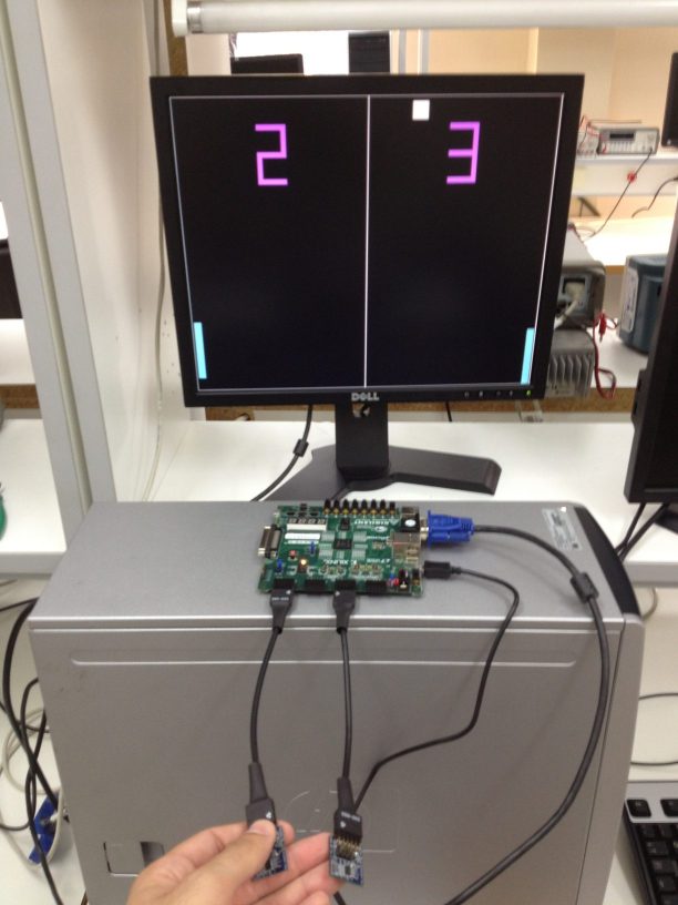
This two person project was completed through the course of Embedded Systems at the University of Thessaly, Department of Computer Engineering. In the context of this project we implemented the classic pong game using a Spartan 6 FPGA, and two 3-axis accelerometers. The code is in Verilog and you can find it on github ( link at the bottom of the page ). The project consists two parts. First, the connection with the monitor through the VGA and game logic and the connection of the accelerometers through the SPI interface.
VGA Technology and Implementation
The first part of the project was to connect the FPGA with a monitor using the VGA output. VGA is a video standard mainly used for computer monitors introduced by IBM in 1987.
VGA video is a stream of frames. Each frame is made of horizontal and vertical series of pixels which are transmitted from top to bottom and from left to right, like a beam is traveling through the screen (CRT displays actually used a moving electron beam, but LCD displays have evolved to use the same signal timings as CRT displays). Information is only displayed when the beam is moving forward and not during the time the beam is reset back to the left or top edge of the display.
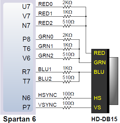
First we made a VGA controller module that generates the correct signals. The signals that we need to pass to the VGA DAC (Digital to Analog Converter) are:
Pixel clock defines the time available to display one pixel of information. With different timing values we can achieve several resolutions, such as 800×600 etc. Vertical sync defines the refresh rate of the display and horizontal sync is used to indicate the end of a horizontal line. We use two counters, hcount and vcount that count the pixels in the horizontal and vertical lines. We can determine the location of a pixel in the screen (x,y) by combining these two counters.
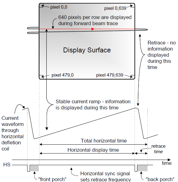
Each line of the video begins with an active video region, in which RGB values are output for each pixel in the line. Then a blanking region follows in which a horizontal sync pulse is transmitted in the middle of the blanking interval. The interval before the sync pulse is known as front porch and after the sync pulse back porch.
There are many VGA timing values that can be used, in order to support several resolutions, as we can see in the table below:
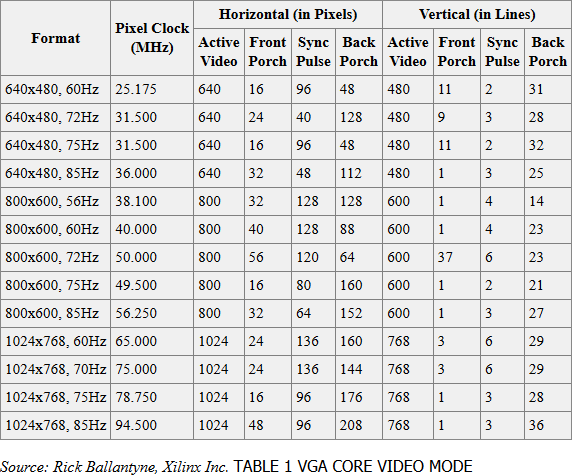
For our project we had a resolution of 800×600@72Hz, so we created a 50 MHz clock, from the 100 MHz clock input of the Spartan 6 and the horizontal and the vertical count have a total value of 1039 and 665 respectively. Based on these numbers we calculate the exact time that the hsync and vsync are set active high (both signals on this resolution must be active high) and we connect them to the FPGA pins.
Pong Game Link to heading
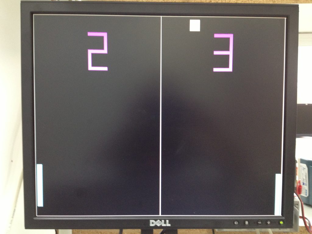
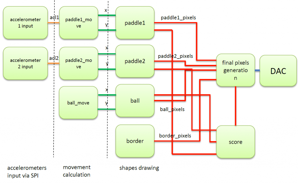
Based on the VGA module we draw on the screen basic shapes such as the paddles and a square dot that represents the ball. The paddle drawing is done at the draw_shape module that given the (x,y) position of the top left pixel, creates a 128×16 pixels rectangle. The same happens with the ball that is 32×32 pixels. Also we have a module that creates the game board; four lines for the perimeter of the screen and one vertical line at the half of the board. Each of these modules, output the pixel locations of each shape. Ball_movement module takes as input the location of the paddles and the ball and does the necessary calculations for the ball movement. Ball moves at a constant speed of one pixel in x axis and one pixel in y axis. If ball hits the up or down board limit or one of the paddles the trajectory is changed. Also in this module we check if the ball hits the right or left limit, and if yes, a signal is generated to indicate that a player has won a point. Whenever a player wins the score is updated and displayed on the screen. If a player’s score reaches 10 points then the game is over and a message indicating which player has lost is shown. Then the game resets to its initial state. Finally this module outputs the pixel locations of the ball and the paddles and they are driven to the output_pixels module that generates the final output that the monitor will display.
A snippet of the code that checks if the ball has hit the paddle:
// Find collision between ball and the paddles
if ( ((ball_y <= paddle1 + 128) && ( (ball_y >= paddle1 - 32) || ( paddle1 <= 32 && ball_y <= 128 ) )) && ball_x == 18 )
sw_x <= 1;

if ( ((ball_y <= paddle2 + 128) && ((ball_y >= paddle2 - 32) || ( paddle2 <= 32 && ball_y <= 128 ) )) && ball_x == 750 )
sw_x <= 0;
The numbers showing the score are in seven segment display format output and are generated in the draw_score module. Also we implemented a pause game function by activating the switch T5. Since Nexys 3 board has a reset button that only erases completely any program loaded, we use switch V8 as a reset signal for our project.
3-Axis accelerometers Link to heading
An accelerometer is an electromechanical device that will measure acceleration forces. These forces may be static, like the constant force of gravity, or they could be dynamic caused by moving the accelerometer. There are different types of accelerometers depending on how they work. Some accelerometers use the piezoelectric effect; they contain microscopic crystal structures that get stressed by accelerative forces, which cause a voltage to be generated. Others implement capacitive sensing, that output a voltage dependent on the distance between two planar surfaces.
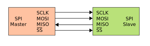
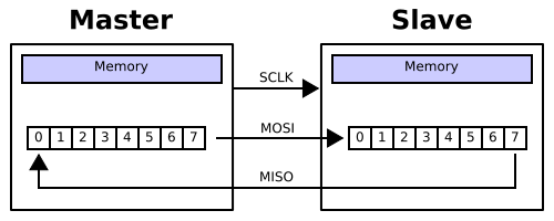
In our implementation we used a 3-axis (one axis for each direction) digital accelerometer powered by the analog device ADXL345 and took advantage of the force of gravity on y axis, making the paddles move by tilting the accelerometer right or left. We connected the accelerometers through the SPI interfaces. SPI operates in full duplex mode and uses four signals: Slave select (SS), serial clock (SCLK), serial data out (SDO), to the accelerometer and serial data in (SDI), from the accelerometer. Devices communicate in master/slave mode where master initiates the data frame. Our setup contains two shift registers, one in the master and one in the slave and they are connected as a ring. Data is shifted out with the most significant bit first, while shifting a new least significant bit into the same register.
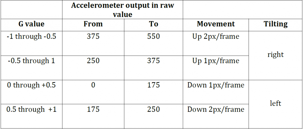
We initialize the transfer with a 5Hz clock and we transmit/receive data at 22.4 kHz rate. The accelerometer is configured for +/- 2g operation. To convert the output to g we have to find the difference between the measured output and the zero-g offset and divide it by the accelerometer’s sensitivity (expressed in counts/g or LSB/g). For our accelerometer in 2g sensitivity with 10-bit digital outputs, the sensitivity is 163 counts/g or LSB/g. The acceleration would be equal to: 𝑎=(Aout−zerog)163 g. We didn’t have to make those calculations for the paddle movement. We just take the accelerometer output and we move the paddles accordingly based on the table below:
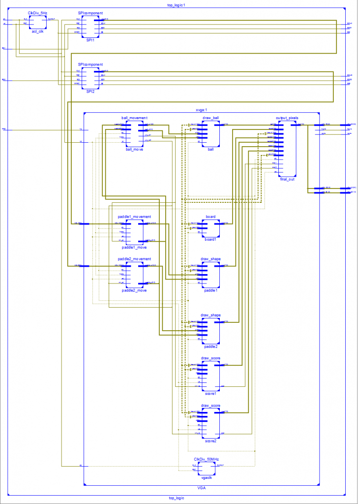
Verilog diagrams Link to heading
In game screenshots Link to heading